TitanPro Cutting
Learning how to upgrade a 3 axis router to 4 axis starts with a clear question: what parts do you need to machine around a central axis? A rotary attachment can turn a flat-bed CNC router into a machine capable of carving columns, handles, and cylindrical reliefs. But adding hardware alone does not create a reliable fourth axis. The controller, drive, CAM software, and workholding must all agree on how the rotary axis moves.
Dr. Yoram Koren is a recognized author on CNC systems and manufacturing. A practical paraphrase of his work—not a verbatim quotation—is that added machine capability matters only when control, mechanics, and process planning work together. That idea guides this overview of seven upgrade paths. You will consider rotary attachments, axis-compatible controllers, motor and drive requirements, CAM post-processors, workholding, and safe clearance checks. A small detail matters: a long workpiece can swing into the router frame even when the cutter appears clear.
The first test may be awkward. Start with a short, low-risk cut in inexpensive stock, then check alignment and dimensions before increasing speed or depth. Some upgrades are straightforward; others expose limits in the router’s frame, spindle, or software. This guide explains what to inspect, what to budget for, and where a professional setup review may help. It also leaves room for a practical truth: not every three-axis router is a sensible candidate for conversion.
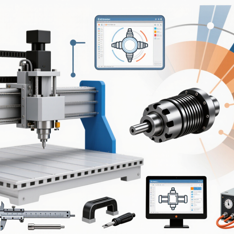
A 3-axis router moves its cutting tool along the X, Y, and Z axes. It can cut profiles, pockets, and reliefs into flat or stationary stock. A 4-axis router adds rotation, usually around the X-axis. The workpiece can turn as the cutter shapes its sides. That changes what the machine can reach.
Some 4-axis work is indexed: the rotary axis turns to a position, then the router cuts with three-axis movement. Other work coordinates rotation and cutting at the same time. The difference matters. A carved wooden spindle may only need indexed cuts, while a twisted form usually needs coordinated motion. Rotary work also requires secure holding, suitable toolpaths, and enough clearance for the stock to turn without striking the table or gantry.
An added axis is not an automatic upgrade for every shop. Flat panels may still be faster and simpler on a 3-axis machine. Check controller compatibility, motor capacity, and software support before changing hardware. Calibration can be fiddly; even a small alignment error may show up as a visible seam. A test cut in inexpensive material can reveal problems early. And sometimes, the extra axis sits unused. That is worth considering.
Understanding the Difference: A typical 3-axis router controls X, Y, and Z linear motion. A 4-axis setup keeps those three axes and adds one rotary axis, often called the A-axis.
This chart compares axis counts, not cutting speed or accuracy. A 4-axis upgrade typically requires a compatible rotary unit, controller support, and CAM software or a postprocessor configured for rotary motion.
A fourth axis adds rotational access, but compatibility starts with the machine itself. Check the controller’s spare outputs, drive capacity, and postprocessor before buying a rotary unit. Measure the table, gantry clearance, and spindle reach with the longest intended workpiece installed. A rotary axis can collide with the gantry even when the bare machine appears spacious. Test the plan in simulation.
Costs extend beyond the axis. Allow for a chuck or tailstock, mounting plate, cabling, controller updates, tooling, and setup time. Ask the supplier for load and runout specifications, then compare them with your largest part and required tolerance. A rough budget should include calibration and operator training; these are easy to underestimate. The right choice depends on repeatable project demand, not the appeal of another axis. Not every part fits.
Deloitte and The Manufacturing Institute’s 2024 workforce study estimated that 1.9 million U.S. manufacturing jobs could go unfilled by 2033. The International Federation of Robotics’ World Robotics 2024 report recorded 4,281,585 industrial robots operating worldwide in 2023, a 10 percent annual increase. These reports describe wider automation pressures, not the payback of a router retrofit. Still, they help explain why shops examine automation while weighing labor and throughput. Compare your current cycle time with a realistic rotary setup, including loading and finishing. Run a test cut on a representative part before committing.
A fourth axis can mean a simple rotary indexer or a fully coordinated A-axis. The right choice depends on part size, controller support, and how often the work must rotate during cutting. A bolt-on stepper indexer is affordable for occasional positioning, while a servo-driven rotary table offers smoother motion for continuous machining. Check table height and usable travel before buying; a small rotary unit can crowd the toolpath.
Seven approaches suit different shops: add a stepper indexer, install a servo rotary table, use an integrated fourth-axis kit, build a headstock-and-tailstock setup, upgrade the controller and drive, fabricate a custom rotary assembly, or replace the router with a purpose-built four-axis machine. The first is simplest, but may lack torque. A matched kit reduces wiring guesswork. Headstock-and-tailstock support helps with long stock, yet alignment takes care. Custom builds allow unusual fixtures, though backlash can be hard to diagnose. Controller upgrades matter only when the existing hardware can command coordinated motion.
Fortune Business Insights’ CNC machine market report valued the global market at about US$101.22 billion in 2023. That figure describes market scale, not retrofit performance; it cannot tell you which conversion will cut accurately. Test repeatability instead: mark a workpiece, rotate it through several angles, and measure whether features return to position. A dial indicator helps. I would not assume a cheap indexer is precise enough just because it turns smoothly. Check cable clearance, fixture access, and emergency-stop behavior before cutting. One overlooked detail: the rotary axis changes the workpiece’s height.
| Approach | How It Adds a Fourth Axis | Typical Workholding | Best Suited For | Main Advantages | Key Limitations and Checks | Relative Retrofit Effort |
|---|---|---|---|---|---|---|
| 1. Add a bolt-on rotary indexer | A rotary unit is mounted on the machine bed and controlled as a synchronized rotary axis, commonly called the A-axis when it rotates around X. | Collet, chuck, fixture plate, or adapter plate, depending on the unit and part. | Parts that need machining on several sides or indexed features around a central axis. | Can add rotary positioning without replacing the router; suitable for indexed and, with compatible hardware and control, coordinated rotary work. | Check bed space, mounting height, tool clearance, cable routing, axis naming, controller support, and whether the drive is intended for continuous rotation or indexing. | Moderate |
| 2. Install a servo-driven rotary table | A powered rotary table supplies the fourth motion axis and can be commanded in degrees or coordinated with the linear axes. | Table-mounted clamps, a fixture plate, or a compatible chuck. | Flat or block-shaped parts requiring indexed drilling, milling, or repeated features around a face. | Offers a stable mounting surface and can simplify repeatable angular positioning. | Confirm table capacity, allowable load, drive and feedback compatibility, usable rotation range, and that the controller supports the required coordinated motion. | Moderate to high |
| 3. Add a rotary chuck with a tailstock | A chuck grips one end of the workpiece while a tailstock supports the other; the chuck’s rotary drive provides the fourth axis. | Chuck at the drive end and a live or fixed center at the tailstock end. | Long, round workpieces such as turned profiles, rails, and cylindrical components. | Provides support at both ends, which can reduce workpiece deflection compared with holding a long part at one end only. | Align the chuck and tailstock centers carefully. Check part length, diameter, tool reach, center compatibility, and safe clearance before cutting. | Moderate to high |
| 4. Mount the rotary axis horizontally | The rotary centerline is set parallel to the machine bed, allowing the workpiece to rotate lengthwise beneath the spindle. | Chuck, collet, or chuck-and-tailstock arrangement. | Long cylindrical parts, spiral grooves, flutes, and features that wrap around a part’s length. | Provides a natural setup for longitudinal rotary work and can make long-part support easier to arrange. | Requires adequate bed length and vertical clearance. Check that the workpiece cannot collide with the spindle, gantry, or bed during a full rotation. | Moderate |
| 5. Mount the rotary axis vertically | The rotary centerline is oriented vertically, so the part rotates about an axis perpendicular to the machine bed. | Chuck, collet, or fixture plate mounted to the rotary unit. | Compact parts needing circumferential features or machining at several angular positions. | Can use a smaller footprint than a long horizontal setup and provides access around the sides of a compact workpiece. | Check mounting rigidity, workpiece balance, tool clearance, and whether the machine’s Z travel accommodates the rotary unit and part height. | Moderate |
| 6. Retrofit a compatible rotary drive and axis hardware | A motor, drive, wiring, and rotary mechanism are integrated with the existing machine instead of relying on a ready-to-install axis package. | Depends on the designed rotary mechanism; may use a chuck, collet, or custom fixture. | Builders with motion-control experience, custom machine layouts, or unusual workholding needs. | Allows the axis, mounting, and workholding to be tailored to the machine and intended parts. | Requires correct motor sizing, mechanical rigidity, drive tuning, wiring, limit or home sensing where needed, and controller configuration. Backlash and unsafe wiring are important risks. | High |
| 7. Upgrade the controller and motion configuration | A controller or motion system with an available fourth-axis channel is configured to operate a compatible rotary unit; CAM and post-processing settings are updated as needed. | Determined by the rotary hardware paired with the controller. | Machines whose existing control system lacks a usable axis channel or cannot coordinate rotary motion with linear moves. | Can resolve control limitations and enable the machine to interpret fourth-axis commands when paired with suitable hardware. | A controller upgrade alone does not create a physical rotary axis. Verify axis-channel availability, motor-drive compatibility, supported coordinated motion, CAM output, and safe machine limits. | High |
Note: “Fourth axis” generally refers to an additional rotary motion axis. It is often labeled A when rotating around X, but axis naming depends on the machine configuration. Actual capacity, accuracy, rotation range, and compatibility vary by machine and rotary unit; confirm these specifications before purchasing or machining.
Installing and Configuring the Rotary Axis and Control System
A rotary axis turns a three-axis router into a practical fourth-axis machine. Mount it firmly, with its centerline parallel to the machine’s X-axis or Y-axis, according to your intended setup. Check alignment with a dial indicator against the chuck or a test bar. Small errors matter. A tilted axis can produce tapered cuts, even when the toolpath looks correct.
The control system needs equally careful setup. Confirm the motor’s steps per revolution, reduction ratio, direction, and axis assignment before cutting. Then configure rotary units and the postprocessor to match your controller. The International Federation of Robotics reported 4,281,585 industrial robots operating worldwide in 2023, a 10% increase from 2022, in its World Robotics 2024 report. That figure is not specific to routers, but it reflects the wider move toward integrated motion systems. Wiring and configuration deserve proper attention.
Test with the spindle off. Move the rotary axis slowly through a full turn, check cable clearance, and verify homing and travel limits. Use a marked scrap cylinder for a shallow test cut; confirm that the engraving wraps evenly. Test slowly. Keep notes on the settings that work. One easy-to-miss detail is the workpiece’s center height: a small offset can distort the cut. Even a carefully aligned machine may need another adjustment.
Before cutting, test the added rotary axis unloaded, then repeat with a secured test piece. Check rotation direction, backlash, cable clearance, and whether the tool tip returns to the same point. ISO 230-2:2014 defines bidirectional positioning tests for numerically controlled axes, including positioning accuracy and repeatability. Use that framework rather than trusting a single home-position check. Small errors compound. For example, a 0.1-degree angular error shifts a point about 0.17 mm at a 100 mm radius. Record actual readings, not just controller settings.
Calibration should include the probe or indicator, its mounting, and the workpiece reference surface. Report measurement uncertainty alongside results; NIST Technical Note 1297 describes expanded uncertainty using a coverage factor, commonly k=2 for roughly 95% coverage under appropriate assumptions. That figure is not a guarantee for every setup. A loose fixture or uneven stock can overwhelm careful axis calibration. Keep hands clear during powered motion, and test the full rotary envelope at low speed before machining. I still recheck after tightening the fixture; it feels redundant, but skipped checks are easy to regret.
A 3-axis router moves its cutter along X, Y, and Z. A 4-axis router also rotates the workpiece, usually around the X-axis.
It helps shape sides of cylindrical or turned stock. A wooden spindle may need only indexed cuts. Twisted forms may need coordinated rotation and cutting.
No. Flat panels are often simpler and faster on a 3-axis machine. Sometimes the extra axis sits unused.
Check controller outputs, drive capacity, and software support. Measure table space, gantry clearance, and spindle reach with your longest workpiece installed.
Budget for a chuck or tailstock, mounting plate, cabling, tooling, calibration, and training. Setup time is easy to underestimate.
A stepper indexer can suit occasional positioning, while a servo rotary table may offer smoother continuous motion. Check torque and table height.
Mark a test piece, rotate it through several angles, then measure whether features return to position. A dial indicator helps. Test it first.
Small alignment errors can leave visible seams. Check cable clearance, secure holding, and emergency-stop behavior before cutting. Calibration can be fiddly.
Upgrading a 3-axis router to 4-axis capability can open up new ways to machine cylindrical and more complex parts. This guide explains how the two configurations differ and how to decide whether an existing router is suitable for conversion. It considers machine compatibility, project needs, expected costs, and the practical trade-offs among seven approaches to adding a rotary axis, from choosing a compatible unit to adapting the control setup.
The article also outlines how to install and configure the rotary axis and connect it with the control system. After installation, careful testing helps confirm that the added axis moves as intended and that its settings are calibrated to the machine and workpiece. By checking motion, alignment, and workpiece security before machining, readers can make a more informed plan for how to upgrade a 3 axis router to 4 axis and reduce avoidable setup problems.