TitanPro Cutting
A gantry can look square and still engrave out of alignment. On a wide machine, even a small angular error can shift the beam across the workpiece, leaving lettering crisp at one end and visibly doubled at the other. The effect often appears only on long jobs. That makes setup checks worth the time.
For a reliable technical baseline, ISO 230-1 describes methods for testing machine-tool geometric accuracy, while ISO 230-2 covers positioning accuracy and repeatability of numerically controlled axes. These standards provide measurement procedures, not a universal tolerance for every engraver. The material, machine design, and job size still matter.
Why is the gantry alignment critical for large scale engraving? Because alignment connects motion accuracy to the mark on the material. Metrology pioneer William Thomson, Lord Kelvin, captured the value of measurement: “When you can measure what you are speaking about, and express it in numbers, you know something about it.” A straightedge, dial indicator, and test pattern can reveal problems that a visual inspection misses. Check both ends of the gantry, compare readings across its travel, and repeat the test after adjustments. Small differences matter.
There is no single adjustment that suits every frame. Belts may settle, rails may vary, and a heavy workpiece may change how the bed sits. That uncertainty is easy to underestimate. A measured, recorded alignment check gives operators a practical reference—and a chance to catch drift before it becomes a costly, visible defect.
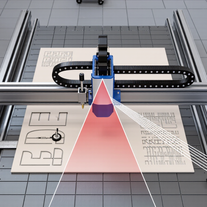
Large-scale engraving makes small alignment errors visible. A gantry that is slightly skewed can produce uneven line spacing, blurred corners, or different engraving depths across the bed. Check the machine cold, then repeat after it has warmed up. Metal frames expand. That matters.
ISO 230-2:2014 sets out methods for measuring positioning accuracy and repeatability on numerically controlled axes. Apply the same measurement discipline to both sides of the gantry: record positions at several points, approach each point from both directions, and compare results. For a 2,000 mm span, a measured 0.5 mm difference between ends equals 0.25 mm per metre. That is a calculation, not a universal tolerance; acceptable error depends on the material, lens, and detail size. Use a dial indicator or a straightedge with a feeler gauge, and check both diagonals for squareness.
A practical setup begins with clean rails and firm fasteners. Move the gantry slowly, watching for binding or a changing gap beneath the bridge. Recheck after tightening; bolts can pull a frame out of alignment. Keep a simple log of readings and room temperature. The first pass may look convincing. It may still be wrong. I would not trust one measurement alone. Compare repeated readings before engraving a full sheet, and treat unexplained variation as a reason to inspect the frame, belt tension, and supports.
Before checking gantry alignment, prepare a stable, uncluttered work area. Place the engraver on a rigid bench, then check that the machine sits level and does not rock. Remove dust and scraps from the rails, wheels, and work surface; even a small chip can affect movement. Switch off and unplug the machine before inspecting or adjusting mechanical parts. Follow its operating instructions, especially when accessing belts or carriage fasteners.
Secure a flat test board on the bed, with no clamps or edges in the gantry’s travel path. Check that the board itself is not warped. Keep a reliable square and measuring tape nearby, and use the same reference points on both sides of the frame. Move the gantry gently by hand only if the machine’s instructions allow it. It should travel smoothly, without catching or noticeable wobble. A common oversight is measuring from different frame edges, which can make accurate readings look inconsistent. Alignment may need more than one pass; I would rather recheck a measurement than force a correction. Small details matter. Keep the work area clear while testing.
On a large engraving bed, small alignment errors can grow across the work area. Check rail parallelism before adjusting the gantry. Place a dial indicator on the moving assembly, then measure the same reference surface at several points along each rail. Record the readings rather than relying on memory. A steady change from one end to the other may indicate misalignment; sudden variation can point to dirt, a damaged surface, or loose mounting hardware. Clean the contact areas and repeat the measurements. One reading is not enough.
Even careful measurements can be tedious. Skipping a repeat is tempting, but it can leave a slight twist unnoticed. If readings disagree, pause and inspect the setup before forcing an adjustment. Alignment should be confirmed with the machine settled, the rails clean, and the measuring tool held consistently. Small errors matter.
Large-scale engraving makes small alignment errors visible. A slightly skewed gantry can leave diagonal lines uneven or cause the carriage to bind near one end. Before adjusting anything, switch off the machine and follow its service instructions. Check that the frame is stable and the rail surfaces are clean; a thin layer of dust can affect measurements.
Loosen the rail fasteners only enough to allow careful movement. Measure between matching points at both ends, or compare the frame diagonals if the machine design permits. Adjust the rails until they are parallel, then square the gantry across them. Tighten fasteners gradually, alternating sides, and recheck measurements as you go. This part can feel fussy. It is easy to rush, and even a careful adjustment may shift slightly during tightening. Move the gantry through its full travel by hand, with power off, and watch for changes in resistance. Finish with a small test grid and inspect its corners and spacing.
Tips: Use the same reference points each time. Keep measurements written down. If the gantry still binds, stop and check for a bent rail or loose frame joint rather than forcing movement.
A small gantry error can become obvious across a large engraving. Before production, secure a test sheet that matches the intended workpiece in size and thickness. Mark its center and corners, then engrave a light grid, a large rectangle, and two corner-to-corner diagonals. Keep the material flat and firmly held. Check whether the lines meet cleanly and whether the rectangle’s opposite sides measure equally. Corners tell the story. A mismatch may point to skew, belt tension differences, or movement in the frame.
Tips: Measure both diagonals with a reliable ruler or caliper. Compare the engraved grid with your design dimensions, not just by eye. Photograph the test and record any adjustments. Recheck focus and material hold-down before blaming alignment.
If the diagonals differ, adjust the gantry according to the machine’s service procedure, then engrave the same pattern again. Change one setting at a time; otherwise, it becomes hard to identify what helped. Inspect the center and edges, since an engraving may look accurate in the middle but drift near a corner. I would not trust a single test, especially after moving the machine or changing its work surface. Repeat the test after adjustments, and use the measured result to decide whether the setup is ready.
Illustrative commissioning record for a 3,000 × 1,500 mm engraving bed. Run a full-scale test pattern, measure it after engraving, and compare the results with the tolerances specified for the machine and project.
| Alignment Check | Test Method / Nominal Dimension | Measured Result | Deviation | Example Acceptance Limit | Result |
|---|---|---|---|---|---|
| Test pattern coverage | 2,800 × 1,300 mm rectangle, positioned inside the usable work area | Engraved across the full specified span | — | Pattern fits within the safe work area | Pass |
| X-axis scale accuracy | 2,800.0 mm test line | 2,801.1 mm | +1.1 mm | ±2.0 mm | Pass |
| Y-axis scale accuracy | 1,300.0 mm test line | 1,299.6 mm | −0.4 mm | ±1.0 mm | Pass |
| Gantry squareness | Compare diagonals of the 2,800 × 1,300 mm engraved rectangle; theoretical diagonal ≈ 3,083.8 mm | D1: 3,083.8 mm; D2: 3,084.4 mm | 0.6 mm diagonal difference | ≤1.0 mm difference | Pass |
| Rail parallelism | Measure rail spacing at the left, center, and right positions | Variation across measured positions: 0.3 mm | 0.3 mm | ≤0.5 mm across the measured span | Pass |
| Corner-to-corner registration | Check engraved corner markers against the programmed pattern coordinates | Maximum positional offset: 0.8 mm | 0.8 mm maximum | ≤1.0 mm | Pass |
| Return-to-position repeatability | Command the gantry to the same reference point five times and measure the position spread | Maximum spread: 0.2 mm | 0.2 mm | ≤0.3 mm | Pass |
Note: The readings and acceptance limits shown are illustrative. Confirm measurement procedures and tolerances against the machine specifications, material, engraving process, and project requirements.
Small errors can create uneven line spacing, blurred corners, or inconsistent engraving depth across a large workpiece.
Place it on a rigid bench and check that it sits level without rocking. Clean dust and scraps from rails and wheels. Unplug the machine before inspecting mechanical parts.
Use a dial indicator, straightedge, feeler gauge, reliable square, and measuring tape. Keep the same reference points on both sides.
Measure both diagonals of the frame or test pattern. Compare the readings. A difference may indicate skew, but it is not automatically a universal tolerance.
Readings at several positions can reveal errors that one measurement misses. Approach each point from both directions and compare repeated results.
Use a flat, secured test sheet matching the intended workpiece. Engrave a light grid, a large rectangle, and two corner-to-corner diagonals.
Follow the machine’s service procedure and change one setting at a time. Then engrave the same pattern again. Corners can be revealing.
Check the machine when cold and again after it warms up. Repeat after adjustments or moving the machine. One convincing test may still be wrong.
Accurate gantry alignment is essential when engraving large workpieces because even minor mechanical errors can create uneven lines, distorted shapes, or inconsistent results across the finished surface. Understanding why is the gantry alignment critical for large scale engraving helps clarify the process: the rails must remain parallel, and the gantry must sit square to the machine’s travel direction. Before making adjustments, prepare the engraver and work area by securing the machine, clearing debris, and checking that the relevant components are accessible.
Measure rail parallelism and gantry squareness with suitable measuring tools, comparing readings at multiple points along the travel path. If the measurements reveal a mismatch, adjust the rails or gantry gradually and recheck each change to avoid introducing new errors. Once the readings are consistent, run a full-scale test engraving on suitable material. Inspect the result across the entire working area and make any final adjustments needed for uniform, reliable output.