TitanPro Cutting TitanPro Cutting

China Best CNC How to Convert 2D Designs into 3D Carving Paths?

Time:2026-09-06 Author:Liam
0%

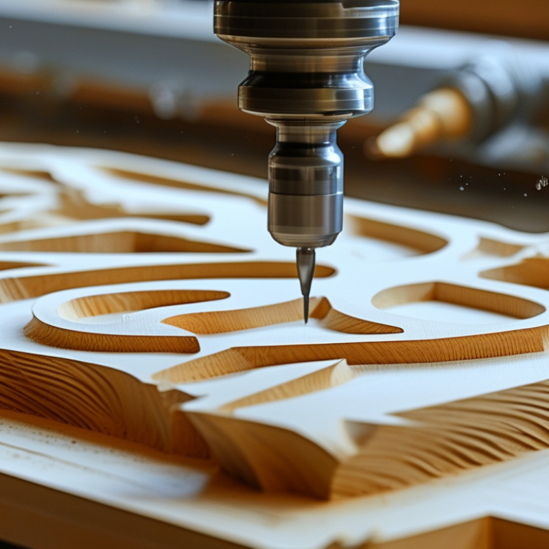
Turning a flat drawing into a detailed relief requires more than pressing an export button. This guide explains how to convert 2d designs into 3d carving paths with practical CNC methods. It follows the workflow used by experienced designers, programmers, and machine operators.

The process usually begins with a clean vector file, such as a DXF or SVG. Open shapes, duplicate lines, and unclear dimensions can create failed toolpaths. Small errors matter. A two-millimeter gap may become a visible break in the final carving.

The design must then receive depth information. Raised areas, recessed borders, rounded transitions, and sharp edges need separate height values. CAM software can build these details through relief modeling, mesh editing, or profile-based operations. Choose a suitable cutter for every feature. A flat end mill removes broad areas efficiently. A ball-nose cutter produces smoother curved surfaces.

Toolpath settings also depend on the material. Wood, acrylic, aluminum, and composite boards respond differently to cutting pressure and heat. Feed rate, spindle speed, step-over, and cutting depth should be tested carefully. Simulate the path before machining. Check for collisions, missing regions, excessive fine detail, and unwanted marks.

A preview can look perfect and still fail on the machine. That is why dry runs, workholding checks, and measured zero points remain important. Real results also depend on cutter sharpness, machine rigidity, and operator judgment. The workflow is not perfectly linear. It often requires revising the model after a test cut.

Reliable CNC production combines software accuracy with hands-on inspection. With disciplined preparation, China Best CNC users can create cleaner, safer, and more repeatable 3D carvings from ordinary 2D artwork.

China Best CNC How to Convert 2D Designs into 3D Carving Paths?

Understanding 2D Design Files and CNC Carving Requirements

A reliable 2D-to-3D CNC workflow begins with the design file, not the carving software. DXF and SVG files usually contain lines, arcs, and closed contours. Raster images contain pixels, so they need tracing before toolpaths can be created. Check scale, units, open vectors, duplicate lines, and missing layers. A one-millimeter error can become obvious on a cabinet door.

The design must also define depth. A 2D outline alone cannot tell the machine whether to cut 3, 6, or 12 millimeters deep. Assign pockets, profiles, islands, and engraving areas separately. Then choose a cutter diameter, feed rate, plunge rate, stepover, and safe height. Narrow details may disappear when the tool is too wide. They often do. Simulate the path and inspect the stock from several angles. I still review the first pass manually because clean geometry can hide an incorrect origin or reversed contour.

Grand View Research valued the global CNC machine market at about 88.56 billion dollars in 2023, showing the growing importance of digital machining skills. The World Economic Forum’s Future of Jobs Report 2025 estimates that 39% of current worker skills may change by 2030. That shift makes file preparation and verification practical production skills, not minor software tasks. A useful habit is exporting a small test path first. It exposes scaling mistakes before valuable material is cut.

China Best CNC How to Convert 2D Designs into 3D Carving Paths? - Understanding 2D Design Files and CNC Carving Requirements
Conversion Stage 2D Design Data Essential File and Geometry Requirements Typical CNC Preparation Expected Result
1. Confirm the Design Format DXF DWG SVG PDF Use a vector-based drawing whenever possible. Raster images such as JPEG or PNG contain pixels rather than editable cutting paths and normally require tracing. Import the file into CAD or CAM software and verify that the drawing scale is not changed during import. A readable 2D design with editable lines, arcs, circles, and closed contours.
2. Set Units and Scale Drawing dimensions, unit symbols, and overall width and height. The design should use one consistent unit system. Common CNC units are millimeters or inches. Imported files may be interpreted incorrectly if the unit is missing. Confirm at least one known reference dimension, such as the total design width or the diameter of a hole. Correct physical dimensions and fewer risks of oversized or undersized machining.
3. Clean the 2D Geometry Open contours, duplicated lines, overlapping segments, fragmented curves, and unwanted construction lines. Profiles intended for cutting should form closed, non-intersecting contours. Duplicate geometry can cause repeated machining or incorrect toolpaths. Join connected segments, remove duplicates, close small gaps, and delete dimensions or guide lines that are not part of the finished shape. Valid, continuous geometry suitable for pocketing, profiling, engraving, or relief generation.
4. Define the Material and Stock Material type, stock length, stock width, and stock thickness. The stock must be large enough to contain the complete design, including clamping clearance. Material properties influence cutting speed, tool selection, and depth of cut. Enter the actual stock size and establish the work origin at a repeatable location, such as a corner, center, or top surface. A machining setup that reflects the real workpiece and reduces positioning errors.
5. Convert Lines into Machining Features Closed profiles, pockets, engraved lines, islands, and internal cutouts. A line alone does not specify whether the tool should cut on the line, inside the boundary, outside the boundary, or remove the enclosed area. Assign a machining operation: profile cutting, pocketing, V-carving, engraving, drilling, or contour finishing. Clearly defined cutting behavior for every design element.
6. Add Z-Axis Information 2D boundaries plus intended engraving depth, pocket depth, or relief height. A 2D drawing normally contains X and Y coordinates only. A 3D carving path requires Z-depth values or a height map to describe vertical variation. Set the top surface as Z = 0 or another defined datum, then specify safe height, cutting depth, maximum depth, and step-down values. A three-axis toolpath containing coordinated X, Y, and Z movements.
7. Select the Cutting Tool Detail size, minimum internal radius, material, and required surface finish. The tool diameter must fit the smallest internal feature. A smaller tool reaches finer details but generally requires more machining time and may be less rigid. Typical options include flat end mills for pockets, ball nose cutters for 3D finishing, V-bits for tapered engraving, and drills for round holes. A tool selection that balances detail, strength, cutting time, and surface quality.
8. Create Roughing and Finishing Paths 3D model, relief height map, or depth-defined 2D features. Roughing removes most excess material, while finishing uses smaller movements and often a smaller tool to improve the final surface. Use a larger cutter for roughing where possible, leave a small machining allowance, then apply parallel, raster, contour, or waterline finishing strategies. More efficient material removal followed by a smoother and more accurate finished surface.
9. Set Cutting Parameters Tool diameter, flute count, material, spindle capability, and machine rigidity. Feed rate, spindle speed, plunge rate, step-over, and step-down must be matched to the material and cutter. There is no single safe value for every CNC machine. Begin with conservative values from the tool supplier or machine documentation, then verify chip load, tool deflection, heat, and cutting sound. A practical balance between cutting safety, productivity, tool life, and surface finish.
10. Simulate and Check Clearances Generated toolpath, stock model, fixtures, clamps, and machine travel limits. The simulation should show the complete stock removal process and identify collisions, excessive depths, unreachable details, and rapid movements near fixtures. Review tool engagement, cut order, retract heights, workholding clearance, and whether the tool can reach all required areas. A verified toolpath with reduced risk of collision, gouging, incomplete cutting, or fixture damage.
11. Post-Process the Toolpath Verified CAM toolpath and machine control requirements. The output code must match the controller format, axis configuration, units, tool-change method, and machine operating limits. Select the correct post-processor, check the generated code, and confirm feed units, spindle commands, safe moves, and tool numbers. Machine-readable G-code or another controller-compatible NC file.
12. Perform a Test Cut Final toolpath, sample material, workholding setup, and zero position. A small test area or inexpensive sample can reveal scaling, origin, depth, tool selection, and surface-finish problems before production. Verify the first movement above the workpiece, use a controlled feed override when appropriate, and measure critical dimensions after cutting. A confirmed process ready for the final workpiece, with documented corrections if required.
Practical note: A 2D design defines the X-Y shape, while a 3D carving path additionally requires Z-axis depth or height information. Cutting parameters should always be validated against the specific material, tool, machine, and workholding method.

Preparing Vector Geometry for Accurate 3D Toolpath Conversion

China Best CNC How to Convert 2D Designs into 3D Carving Paths?

Preparing Vector Geometry for Accurate 3D Toolpath Conversion

Accurate 3D carving begins with clean vector geometry. Import the 2D drawing into your design software, then confirm its scale and measurement units. A line that looks closed may contain a tiny gap. That gap can stop a pocket or create an unexpected cutting path. I usually zoom in closely and inspect every corner, especially around letters and narrow shapes. Remove duplicate lines, overlapping curves, and hidden objects before assigning any depth.

Convert outlines into closed profiles whenever possible. Closed geometry gives the toolpath generator a clear boundary. Separate engraving lines from filled regions using organized layers. Then assign practical Z-depths to each region. For example, a shallow groove may need 1 mm, while a recessed area may require several passes. Avoid sharp depth changes unless the cutter and material can handle them. I still miss small nodes occasionally, so a preview is never optional. Simulate the path and check for gouges, uncut corners, or movements above the work surface.

Tips: Use simple geometry first. Reduce unnecessary nodes, but preserve important curves. Set the origin near a repeatable corner. Preview with the actual cutter diameter. Make a small test carving before cutting the final workpiece. Material thickness can vary, and that detail is easy to overlook. Record successful settings for future projects.

Selecting CNC Software and Defining the Carving Parameters

A clean 2D drawing is only the beginning. To create a reliable 3D carving path, choose software that imports vectors accurately and supports layered reliefs. In workshop trials, I check closed shapes, duplicate lines, and missing curves before modeling. Small errors can produce visible ridges. They are easy to overlook.

Set the project units, material size, and Z-zero position before selecting a toolpath. A roughing path removes bulk material with a larger cutter and leaves a small finishing allowance. For detailed surfaces, a smaller ball-nose cutter usually produces smoother transitions.

Define cutting depth, stepover, feed rate, plunge rate, and spindle speed according to the material and tool diameter. Conservative settings are safer. However, excessive caution can create heat and wasted time.

Always simulate the path in three dimensions. Look for gouges, uncut corners, unexpected lifts, and movement beyond the stock. I also run a shallow test on scrap material, because real wood grain or plastic hardness may differ from software assumptions. The first result is rarely perfect. I still adjust stepover after seeing faint tool marks under angled light. Save the verified settings with the material and cutter information, then confirm the machine origin before carving the final piece.

Generating, Simulating, and Refining the 3D Carving Toolpaths

China Best CNC: How to Convert 2D Designs into 3D Carving Paths?

Generating, Simulating, and Refining the 3D Carving Toolpaths

Converting a 2D drawing into a 3D carving path starts with clean geometry. Remove duplicate lines, open contours, and accidental overlaps before importing the design into CAM software. Assign measured depths to each region, then create height transitions between shallow details and the main surface. A relief model should reflect the cutter’s diameter, material hardness, and machine limits. Small details may disappear when the tool is too large.

Generate a roughing path with a larger cutter to remove excess material efficiently. Leave a small allowance for finishing. Then create a finishing path with closer stepovers and a smaller tool. I usually inspect the cutting direction, plunge points, and safe travel height before exporting machine code. Small mistakes matter.

Simulation reveals problems that a flat drawing cannot show. Watch for collisions, uncut corners, excessive tool lifts, and sharp depth changes. Compare the simulated surface with the intended relief under different lighting angles. A smooth preview can still hide weak geometry or unrealistic tool movement. This is where practical experience becomes important.

Refinement is rarely perfect on the first attempt. Reduce the stepover when curved surfaces show visible ridges, but check machining time and heat buildup. Adjust feed rates gradually after testing on scrap material. Keep the original file, simulation record, tool settings, and inspection notes together. That habit improves repeatability and makes future corrections more reliable.

Exporting G-Code and Running the CNC Carving Process Safely

Converting a 2D drawing into a reliable 3D carving path starts with disciplined G-code preparation. Set the correct units, origin, tool diameter, cutting depth, and safe Z height before exporting. A small mismatch can turn a shallow relief into a broken tool. I always compare the toolpath preview with the original drawing. It is not glamorous, but it catches careless errors.

The U.S. Bureau of Labor Statistics recorded 5,283 fatal occupational injuries in 2023, showing why machine control deserves constant attention. This figure covers all industries, not CNC work alone. Still, it is a serious warning. Before cutting, inspect the exported G-code line by line near plunges, rapid moves, and boundary edges. Use a verified postprocessor, then run the program in simulation. Check the coordinate system again. I sometimes find an incorrect negative value after feeling confident.

Safety controls must be practical. Secure the stock firmly, confirm the cutter is tight, and remove loose tools from the table. Use guarding, eye protection, hearing protection, and suitable dust extraction.

OSHA machine-guarding guidance under 29 CFR 1910.212 supports protecting operators from moving parts and flying debris. Start with a dry run above the material, then use single-block mode and reduced feed override for the first passes. Keep one hand near the emergency stop, but never reach across a moving spindle. The first cut should be treated as a test, not a performance.

FAQS

: Which 2D file types work well for CNC carving?

: DXF and SVG files usually work well. They contain lines, arcs, and closed contours. Raster images need tracing first.

What should I check before importing a design?

Check scale, units, open vectors, duplicate lines, and missing layers. A one-millimeter error can show clearly on a cabinet door.

Can a 2D outline define the carving depth?

No. A flat outline cannot specify three, six, or twelve millimeters. Assign depths to pockets, profiles, islands, and engraving areas.

How do I choose suitable cutting parameters?

Consider cutter diameter, feed rate, plunge rate, stepover, and safe height. Narrow details may disappear with an oversized cutter.

Why should I create roughing and finishing paths separately?

A larger cutter removes excess material quickly. Leave a small allowance, then use a smaller cutter for surface finishing.

What does simulation reveal?

Simulation can expose collisions, uncut corners, excessive tool lifts, and sharp depth changes. Inspect the preview from several angles.

How can I reduce visible ridges on curved surfaces?

Reduce the stepover gradually. Check machining time and heat buildup. A smaller stepover usually improves smoothness.

What should I review before exporting machine code?

Inspect cutting direction, plunge points, safe travel height, and the machine origin. A reversed contour can ruin an otherwise clean design.

Is the first toolpath always reliable?

No. Test a small path on scrap material. I still review the first pass manually because simulation can hide weak geometry.

Conclusion

Converting 2D designs into precise 3D carving results begins with understanding the source file and the requirements of the CNC machine. Clean vector geometry, closed contours, consistent scale, and properly defined layers help prevent gaps, overlaps, and unintended cuts. The design must then be prepared for depth information, including carving regions, height levels, and suitable boundary details.

The process of how to convert 2d designs into 3d carving paths involves selecting suitable CNC software, setting the material thickness, carving depth, tool type, feed rate, spindle speed, and step-over. After generating the toolpaths, users should simulate the cutting process to identify collisions, missed areas, or excessive machining time, then refine the parameters as needed. Finally, the verified G-code can be exported and transferred to the CNC machine. A safe setup, secure workholding, correct tool installation, and careful monitoring are essential for achieving accurate and consistent 3D carvings.

Liam

Liam

Liam is a dedicated marketing professional with a profound expertise in the industry, where he excels at highlighting the unique advantages of our core products. With a keen understanding of market trends and consumer needs, Liam frequently updates our company’s professional blog, providing......